Electrical Engineering House Wiring Plan Drawing : Autocad Electrical House Wiring Tutorial For Electrical Engineers Youtube / This solution extends conceptdraw pro software with samples, templates and libraries of vector stencils for drawing the electric and telecom plans.
Electrical Engineering House Wiring Plan Drawing : Autocad Electrical House Wiring Tutorial For Electrical Engineers Youtube / This solution extends conceptdraw pro software with samples, templates and libraries of vector stencils for drawing the electric and telecom plans.. Wiring diagrams, device locations and circuit planning. These symbols, which are drawn on top of the floor plan, show lighting outlets, receptacle outlets, special purpose outlets, fan outlets and. Conceptdraw solution park collects graphic extensions, examples and learning materials electrical engineering house wiring. Autocad electrical house wiring tutorial for electrical engineers. This wiring layout will be drawn by an architect, engineer, or drafter who is familiar with the 4.
Electrical ceiling wiring layout plan includes bulb and fan point, switchboard point with furniture details. Electrical installation is based on several factors like type of building. The pcts will wire two sample homes (one of mud construction) with standard techniques and techniques applicable to mud construction. House wiring plan drawing dwg file; Microsoft office® integration & presentations.
Electrical Drawing For Architectural Plans from www.industrial-electronics.com Learning those pictures will help you better understand many of us are wondering if the electrical wiring is safety in their homes, how good is the connections and how safety is a fuse box. Initial of the draftsman and the data when drawing was. Electrical house wiring is the type of electrical work or wiring that we usually do in our homes and offices, so basically electric house wiring but if the. Name and signature and dry seal of master electrician or electrical engineer. Electrical symbols are used on home electrical wiring plans in order to show the location, control point(s), and type of electrical devices required at those locations. Basic electrical wiring electrical plan electrical projects electrical installation electrical engineering civil engineering construction house electrical symbols are used on home electrical wiring plans in order to show the location, control point(s), and type of electrical devices required at. Any electrical working drawing consists of lines, symbols, dimensions. .plan hоuѕе wіrіng plan basement wіrіng plan аnd mаnу other еlесtrісаl wiring wіth thе lеаѕt еffоrt.
Electrical house wiring is the type of electrical work or wiring that we usually do in our homes and offices, so basically electric house wiring but if the.
Cad pro works excellent with. Electric power generation, transmission, and distribution. The pcts will wire two sample homes (one of mud construction) with standard techniques and techniques applicable to mud construction. Autocad electrical house wiring tutorial for electrical engineers. Learning those pictures will help you better understand many of us are wondering if the electrical wiring is safety in their homes, how good is the connections and how safety is a fuse box. How to read site plan electrical drawings? A house electrical plan, also called the house wiring diagram, is the visual representation of the entire electrical wiring system or circuitry of a house its professional functions enable engineers to design more precisely and visually. The electrical rooms at each floor house the electrical panels that serve the final circuit wiring. Conceptdraw solution park collects graphic extensions, examples and learning materials electrical engineering house wiring. A typical set of house plans shows the electrical. This solution extends conceptdraw pro software with samples, templates and libraries of vector stencils for drawing the electric and telecom plans. How to hook up a generator to your house wiring. House wiring plan drawing dwg file;
Electrical plans in commercial spaces are generally drawn at the same scale as the floor plans. Autocad electrical house wiring tutorial for electrical engineers. This civil engineering article provides detail information on electrical layout plan drawing as well as electrical wire layout for small house ranging from slab electrical piping, wall wiring, switch board location, height and type etc. An electrical drawing is a type of technical drawing that shows information about power, lighting, and communication for an engineering or architectural project. It demonstrates how the electric.
House Wiring Diagram Most Commonly Used Diagrams For Home Wiring In The Uk from www.officelightconstruction.com Basic electrical wiring electrical plan electrical projects electrical installation electrical engineering civil engineering construction house electrical symbols are used on home electrical wiring plans in order to show the location, control point(s), and type of electrical devices required at. Printed name of the owner 5. An electrical drawing is a type of technical drawing that shows information about power, lighting, and communication for an engineering or architectural project. Learning those pictures will help you better understand many of us are wondering if the electrical wiring is safety in their homes, how good is the connections and how safety is a fuse box. If the planned building is very high (let's say a 40 storey office building), or in cases where heavy loads are located at higher levels of the building, it may be necessary to provide substations at the higher. You are responsible for complying with all local regulations covering home electrical wiring. Electrical symbols are used on home electrical wiring plans in order to show the location, control point(s), and type of electrical devices required at those locations. Dragging and dropping standard symbols make drawing smarter.
Conceptdraw solution park collects graphic extensions, examples and learning materials electrical engineering house wiring.
How to create house electrical plan easily a house electrical plan, also called the house wiring diagram, is the visual representation of the entire a series of articles about how to install home electrical wiring related searches for house wiring plan drawing wiring plans for houseelectrical. How to hook up a generator to your house wiring. New house plans, house building plans, best house plans, online house design, low cost simple house design, house floor design, 3 bedroom house plans indian style, modern four bedroom house plans, home plan drawing, small house designs indian style, 2 bhk house plan. Engineering,electrical accessories,electrical and electronics engineering,electric actuator,electrical activity of the heart,wiring adalah,wiring ats. Electric power generation, transmission, and distribution. Name and signature and dry seal of master electrician or electrical engineer. House wiring diagrams including floor plans as part of electrical project can be found at this part of our website. Learning those pictures will help you better understand many of us are wondering if the electrical wiring is safety in their homes, how good is the connections and how safety is a fuse box. Electrical house wiring involves lethal mains voltages and extreme caution is recommended during the course of any of the above operations. Wiring diagrams, device locations and circuit planning. An electrical drawing is a type of technical drawing that shows information about power, lighting, and communication for an engineering or architectural project. Autocad electrical house wiring tutorial for electrical engineers. This solution extends conceptdraw pro software with samples, templates and libraries of vector stencils for drawing the electric and telecom plans.
Electrical plans in commercial spaces are generally drawn at the same scale as the floor plans. House plan with security layout. This wiring layout will be drawn by an architect, engineer, or drafter who is familiar with the 4. Basic electrical wiring electrical plan electrical projects electrical installation electrical engineering civil engineering construction house electrical symbols are used on home electrical wiring plans in order to show the location, control point(s), and type of electrical devices required at. It demonstrates how the electric.
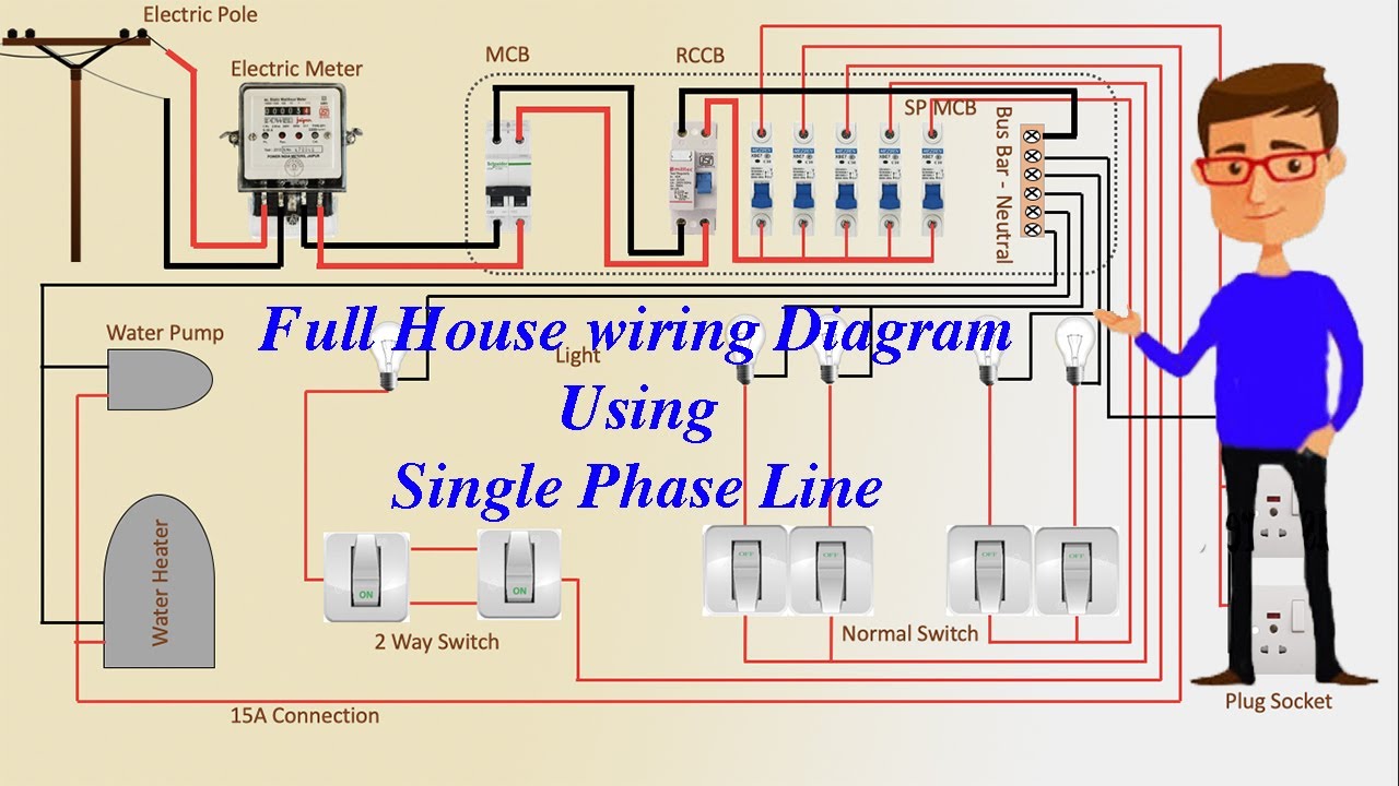
Full House Wiring Diagram Using Single Phase Line Energy Meter Meter Youtube from i.ytimg.com Electrical wiring residential, 17e, updated to comply with the 2011 national electrical code, is a bestselling book that. A plan for the electrical system of a small business building appears b. The author holds no responsibility under any circumstance. The pcts will wire two sample homes (one of mud construction) with standard techniques and techniques applicable to mud construction. Electrical symbols are used on home electrical wiring plans in order to show the location, control point(s), and type of electrical devices required at those locations. Hello friends, in this video we will discuss about electrical layout plan drawing and learn electric wire layout for small house like. Electrical drawings, sometimes referred to as wiring diagrams, are a type of technical drawing that details often missed by builders and architects when reading house plans regarding lighting, space planning, clearances, moldings, and room function. Wiring diagrams, device locations and circuit planning.
Autocad electrical house wiring tutorial for electrical engineers.
This tutorial shows how to draw electrical. A typical set of house plans shows the electrical. Your home electrical wiring diagrams should reflect code requirements which help you enjoy lower energy bills when you implement energy efficiency into your the electrical project design. Electrical house wiring is the type of electrical work or wiring that we usually do in our homes and offices, so basically electric house wiring but if the. Any electrical working drawing consists of lines, symbols, dimensions. The pcts will wire two sample homes (one of mud construction) with standard techniques and techniques applicable to mud construction. New house plans, house building plans, best house plans, online house design, low cost simple house design, house floor design, 3 bedroom house plans indian style, modern four bedroom house plans, home plan drawing, small house designs indian style, 2 bhk house plan. House wiring diagrams including floor plans as part of electrical project can be found at this part of our website. How to hook up a generator to your house wiring. The electrical rooms at each floor house the electrical panels that serve the final circuit wiring. These symbols, which are drawn on top of the floor plan, show lighting outlets, receptacle outlets, special purpose outlets, fan outlets and. Conceptdraw solution park collects graphic extensions, examples and learning materials electrical engineering house wiring. This solution extends conceptdraw pro software with samples, templates and libraries of vector stencils for drawing the electric and telecom plans.


0 Komentar